Set Top Box or STB has become an integral part of TV viewing in many parts of the
world. We commonly see this sleek looking device sitting on side of TVs. Though
this device looks slim and simple but it is one of the most complex embedded systems
today. STBs are increasing their feature set day by day. Few of the common features
in current generation STBs are time shift mode viewing, recording, Internet based
viewing, video on demand, Full High definition video output etc.
STB is very complex embedded system; it consists of 30+ hardware blocks and similar
number of software drivers. STB has lot of computing power distributed across main
processor and various co-processors. In few of top end STBs if we add operating
frequencies of all co-processors then it would be in range of 3-4 GHz.

Hardware
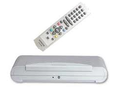
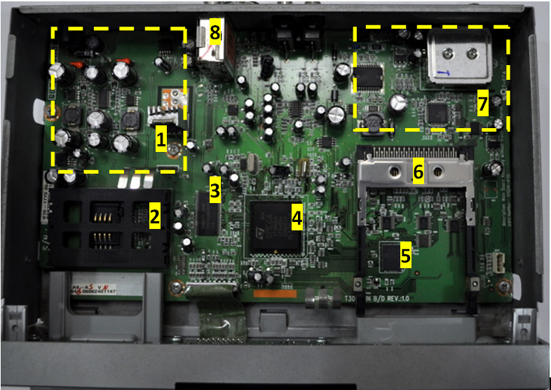
A typical STB would look similar to one shown in following image. This is picture
of standard definition (SD) satellite based STB being used at my home. Number of
components used is fairly less compared to complexity of this system. This credit
goes to the main STB decoder chip which integrates a lot of hardware components
required into a single chip.

Inside view of Satellite Set Top Box
STB blocks
1. Power Supply
2. Smart Card Slot
3. RAM
4. STB Decoder
5. Flash
6. DVB-CI Slot
7. Satellite Front End
8. RF Modulator
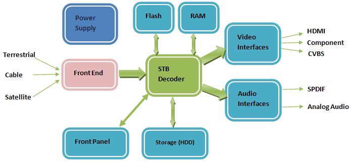
The above picture shows STB circuit board and major components on the board. A more
logical relationship between various components is shown in following block diagram.

Set Top Box Hardware Blocks
STB Decoder: This is heart of the whole system. In current generation
STBs most of the features required by STB system are integrated in STB decoder chips.
This level of integration is called System On Chip (SoC). STB SoCs contain a large
number of blocks ranging from de-multiplexer to decoders and peripherals like USB,
SATA etc.
Front End: Front End part of STB is responsible for receiving the
broadcasted signal, demodulating the signal and outputting digital data output for
STB decoder chip. Depending upon broadcasting environment terrestrial or satellite
or cable front end will be used. Front end unit consist of 3 main blocks tuner to
tune correct frequency, demodulator to demodulate as per standard and forward error
correction (FEC) unit for data recovery.
Power Supply: This is the main power source for board. This unit
generates different voltage required by various components on board. Input to this
unit can be main line AC (220/110) or DC 12V via standalone power adapters.
Flash: This is used to store boot loader, main application and
other user specific non volatile data. Different STBs uses different sizes of flash
ranging from 8MB to 64MB.
RAM: RAM is used to store all intermediate data (such as decoded
video/audio buffers) and application variables. In many cases main application is
also copied to RAM and is executed from RAM to speed up the operation (as RAM is
faster compared to Flash). RAM size ranges from 32MB in standard definition STBs
to 256MB in some top end Full HD STBs.
Video Interfaces: STB decoder chip outputs video data in analog
or digital format. To make these signals compatible with external devices, special
circuitry like filter and physical connector are required. Current generation STBs
provide many video output formats such as CVBS, S Video, Component video and HDMI.
Audio Interfaces: STB decoder chip outputs audio data in analog as well as digital
format. In some cases high quality DACs are used to convert digital data into analog
format. Digital data is also transmitted in digital format using SPDIF standard.
Storage: Few STBs also work as digital video recorders. To aid
storage of programs some storage device (HDD) is added via any of the interfaces
(SATA, eSATA, ATAPI or USB) provided by decoder chip.
Front Panel: This is STBs interface to external world. Front panels
are different for different boxes. But most of them provide IR input/output, Status
LEDs, 7 segments or LCD and few switches to configure set top box. These features
are controlled by parallel IOs of main decoder chip. In some cases a dedicated microcontroller
is added to front end to reduce processing load for main chip and also to reduce
the number of wires going from front panel to main PCB.
DVB-CI Slot: This slot is provided to support various conditional
access schemes. Conditional Access providers provide compatible DVB-CI cards to
be used with STB. The DVB-CI card decrypts the channels encrypted by Conditional
Access provider as per user’s subscription policies.
Smart Card Slot: This slot is provided to use smart card for Conditional
Access implementation. Unique subscriber ID is stored on each card. Smart card is
also used in decrypting the channels.
RF Modulator: This is used to modulate Audio and video into RF
signal. This is mainly to be used with older TVs which have only RF input and no
composite (CVBS) input.
STB Decoder SoC
STB Decoder is one of the most complex system on chip (SoC). There is generally
one main processor and lot of co-processor doing dedicated processing.
A typical decoder SoC will have following blocks.
Set Top Box Decoder blocks
Main CPU: This is the main CPU executing the STB application. It
is a general purpose CPU with lot of development tools available. Its speed range
from 200MHz on standard definition devices to near 1GHz on High Definition devices.
The main CPU is generally based on industry standard core such Super H or ARM to
improve ease of tools and reusable stack availability.
Demux: Demux is a dedicated co-processor to de-multiplex the digital
transport stream into audio, video and other data. Demux checks the input stream
for errors and protocol compliance and filters the required data into desired buffers
(Audio, video)
Video Decoder: This co-processor is responsible for converting
compressed video (MPEG) data into basic video format. Current generation decoders
have programmable video decoders, so video decoders can support a variety of formats
such as MPEG2, H264, VC1 etc.
Graphics Engine: This co-processor is dedicated to graphics acceleration.
Its main task is to draw pictures and menus for user interface (UI). This unit is
becoming more powerful these days with introduction of 3D menus.
Mixer: This block is responsible for mixing the video output and
graphics output and producing a final single image. This is also responsible for
ordering of video and graphics plane and transparency settings. As shown is image
there are two planes one video in background on video plane and other is rectangular
window showing program information on graphics plane. These two planes are mixed
by mixer to generate a single image.
Video Output: Final result after mixing video decoder and graphics
accelerator outputs is provided to video output block. This block is responsible
for outputting data as per required standards (PAL, NTSC, SECAM, HDMI). This block
generates output in analog format using DACs. This block also generates output in
digital format using HDMI convertors.
Audio Decoder: Audio decoder converts the compressed audio data
into basic audio data. Audio decoders are also programmable these days. They can
be programmed to support any audio standard. Audio decoder generally supports MPEG,
AAC, Dolby formats.
Audio Output: Audio output is fed to audio output block. This block
provides audio output in analog format using internal DACs and in digital format
using SPDIF convertor.
Peripherals: Other than main decoders and CPU a lot of peripheral
devices are supported by STB SoCs for providing various features.
USB: For record/playback on external storage
SATA: used to connect HDD for providing digital video recording
facility.
Ethernet: Input source for IP based STBs
UART: Debug port. Sometimes also used for software upgrade in field
I2C: Used by main STB SoC to communicate with external peripheral
devices such as front end, SCART controller, HDMI controller etc.
SPI : Used for connecting to non-volatile storage on serial flash
devices.
Software
STB Software is organized as layered architecture as shown in block diagram
below. RTOS is generally STB company proprietary or some industry standard OS such
as Linux. Software drivers are written for all hardware blocks and some software
components. A typical STB has 30-40 different drivers. Middleware is generally used
to standardize the interfaces from drivers to application so that device independence
can be provided. Final application is on top of middleware and it usually remains
same for one service provider across different STBs.